No products
New products
-

Mini Sanding Block, Printed in White ABS
Doesn't come with sandpaper, photo is just to show it assembled. 3D...
2,89€
Kits
- Active components
- Antennas
- Bargain Packs
- Batteries
- Circuit Prototyping
- Component Selection Packs
- Computer Related
- Blank Media
- Computer PSU's
- Computers (Desktops / Towers)
- CPU's and coolers
- Docking Stations
- Flash Memory
- Graphics Cards
- Hard Disk Donor PCBs
- Hard Disk Spindle Motors
- Hard Disks (Generic)
- Hard Disks (Specific Models /Firmware)
- Input Devices
- Laptop Disk Caddies
- Laptop Display Panels
- Laptop Hinges
- Laptop Keyboards
- Laptop other Spare Parts
- Laptop Power Supplies / Adaptors
- Laptop Wifi cards / modules
- Laptops / Tablets
- Memory Modules
- Monitors
- Motherboard Back Plates
- Motherboards
- Network Cards
- Networking - Routers, Switches, Firewalls e.t.c.
- Other Cards
- Printer Ink (Mostly out of date)
- Removable (Floppy/Optical) Drives
- Sound Cards
- Webcams
- Consumer Products
- Craft Supplies
- Electromechanical
- Adaptors
- Circuit Breakers
- Connectors
- Banana
- Battery connectors / Holders
- Clamps, Croc Clips and Hooks
- Connector Pins
- Connector Shells
- Crimp Terminals
- D Type
- DIN Connectors
- Jack
- Other Connectors
- PCB Headers / IDC Connectors
- Pin extraction tools
- PSU Connectors
- RCA / Phono / Cinch
- RF Connectors
- RJ Connectors
- Screw/Clamp Terminals
- Speaker Connectors
- Test Pins
- USB
- XLR / Cannon
- Din Rail Stuff
- Fans
- Fuse Holders
- Loudspeakers / Sounders
- Mains Connectors / Switches e.t.c.
- Microphones
- Motors / Servos
- Panel Indicators
- Panel Meters
- Pumps
- Relays
- Switches
- Tape Heads
- Used Fans - Clearance
- Interesting Old Stock or Used Items/Modules
- Kits
- Labels / Paper Goods
- Measuring / Test Equipment
- Mechanical Hardware
- 3D Printed Items
- Bearings
- Brackets
- Cable Clips
- Cable ties
- Carabinas
- Compressed Air Fittings
- Cotter / Split Pins
- Drive Belts
- Enclosure Accessories (Handles, Protective corners e.t.c.)
- Enclosures / Boxes
- Eurorack / Subrack Parts
- Fan Guards
- Feet
- Grommets / Strain Reliefs
- Heatsinks
- Hose Clamps / Jubilee Clips
- Knobs
- Locks and accessories
- Magnets
- Nuts
- Other mechanical parts
- PCB Standoffs / Spacers / Pillars
- Pop Rivets
- Screws (Machine)
- Screws (Self Tapping and for Plastic)
- Springs
- Wall Plugs / Anchors / Rawplugs
- Washers
- Modules and Circuit Building Blocks
- Passive components
- Power Supplies
- Sensors
- Services
- Tools
- Wire and Cable
 View larger
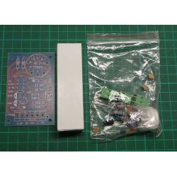
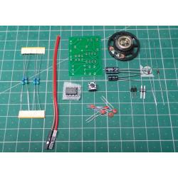
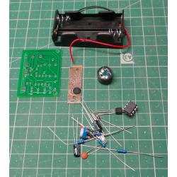
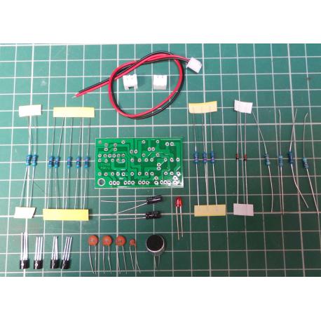
 Clap controlled Switch Kit
KIT014
New product
7 Items
- Send to a friend
- Remove this product from my favorite's list.
- Add this product to my list of favorites.
More info
Clap Acoustic Control Switch Suite Circuit Electronic PCB DIY Kits
Working Principle
- Q1 and Q2 composed of two audio amplifier circuit, the audio signal is accepted by the MK1 C1 is coupled to the base of Q1 pole, amplified and fed directly from the collector to the base of Q2 to a negative square wave at the collector of Q2, with to trigger the bistable circuit.
- R1, C1 circuit frequency response is limited to about 3kHz to high sensitivity range.
- The power is turned on, the state of the bistable circuit Q4 off, Q3 saturated, D3 does not shine.
- When MK1 received control signal, and a negative square wave output after two enlarged, negative spikes through D1 add to the base of Q3, the circuit rapidly flip, D3 is lit after differential processing.
- When MK1 again connected to the control signal, the circuit and flipped, D3 is off. - Circuit board reserved for the terminal J1 access outside the control equipment and other devices through the J1 connector relay voice. (Then relays required at both ends of the relay coil anti and a diode)
Specifications
- Suite Name: Clap switch kit
- Kit Model: PSK-1
- Operating Voltage: 5V
- PCB Size: 28 x 49mm
Reviews
No customer reviews for the moment.
30 other products in the same category:

