No products
New products
-

Mini Sanding Block, Printed in White ABS
Doesn't come with sandpaper, photo is just to show it assembled. 3D...
2,89€
Kits
- Active components
- Antennas
- Bargain Packs
- Batteries
- Circuit Prototyping
- Component Selection Packs
- Computer Related
- Blank Media
- Computer PSU's
- Computers (Desktops / Towers)
- CPU's and coolers
- Docking Stations
- Flash Memory
- Graphics Cards
- Hard Disk Donor PCBs
- Hard Disk Spindle Motors
- Hard Disks (Generic)
- Hard Disks (Specific Models /Firmware)
- Input Devices
- Laptop Disk Caddies
- Laptop Display Panels
- Laptop Hinges
- Laptop Keyboards
- Laptop other Spare Parts
- Laptop Power Supplies / Adaptors
- Laptop Wifi cards / modules
- Laptops / Tablets
- Memory Modules
- Monitors
- Motherboard Back Plates
- Motherboards
- Network Cards
- Networking - Routers, Switches, Firewalls e.t.c.
- Other Cards
- Printer Ink (Mostly out of date)
- Removable (Floppy/Optical) Drives
- Sound Cards
- Webcams
- Consumer Products
- Craft Supplies
- Electromechanical
- Adaptors
- Circuit Breakers
- Connectors
- Banana
- Battery connectors / Holders
- Clamps, Croc Clips and Hooks
- Connector Pins
- Connector Shells
- Crimp Terminals
- D Type
- DIN Connectors
- Jack
- Other Connectors
- PCB Headers / IDC Connectors
- Pin extraction tools
- PSU Connectors
- RCA / Phono / Cinch
- RF Connectors
- RJ Connectors
- Screw/Clamp Terminals
- Speaker Connectors
- Test Pins
- USB
- XLR / Cannon
- Din Rail Stuff
- Fans
- Fuse Holders
- Loudspeakers / Sounders
- Mains Connectors / Switches e.t.c.
- Microphones
- Motors / Servos
- Panel Indicators
- Panel Meters
- Pumps
- Relays
- Switches
- Tape Heads
- Used Fans - Clearance
- Interesting Old Stock or Used Items/Modules
- Kits
- Labels / Paper Goods
- Measuring / Test Equipment
- Mechanical Hardware
- 3D Printed Items
- Bearings
- Brackets
- Cable Clips
- Cable ties
- Carabinas
- Compressed Air Fittings
- Cotter / Split Pins
- Drive Belts
- Enclosure Accessories (Handles, Protective corners e.t.c.)
- Enclosures / Boxes
- Eurorack / Subrack Parts
- Fan Guards
- Feet
- Grommets / Strain Reliefs
- Heatsinks
- Hose Clamps / Jubilee Clips
- Knobs
- Locks and accessories
- Magnets
- Nuts
- Other mechanical parts
- PCB Standoffs / Spacers / Pillars
- Pop Rivets
- Screws (Machine)
- Screws (Self Tapping and for Plastic)
- Springs
- Wall Plugs / Anchors / Rawplugs
- Washers
- Modules and Circuit Building Blocks
- Passive components
- Power Supplies
- Sensors
- Services
- Tools
- Wire and Cable


Digital LED clock Kit, with STC11FC2, 4digit
KIT092
New product
5 Items
- Send to a friend
- Remove this product from my favorite's list.
- Add this product to my list of favorites.
More info
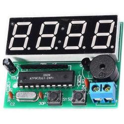
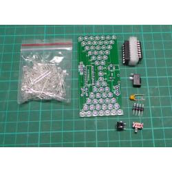
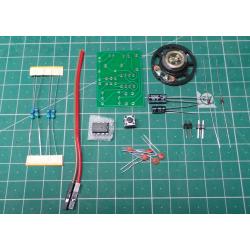
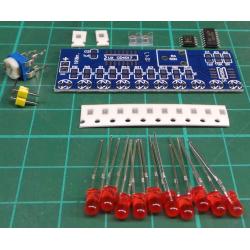
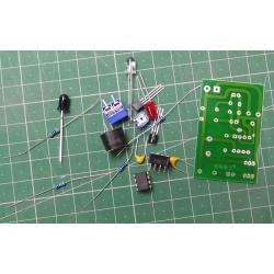
Digital LED clock with STC11FC2
Build:
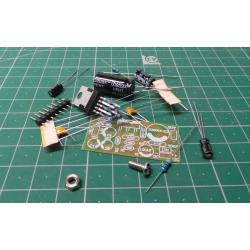
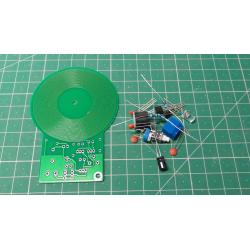
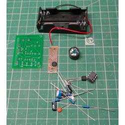
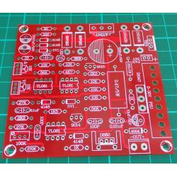
The clock is implemented on a single-sided printed circuit board. The components needed to assemble the watch are divided into several groups and should be installed in this order
1. Resistors
2. Capacitors
3. Crystal
4. Resistor array
5. Transistor
6. Microswitches, piezo and terminal blocks
7. LED display
8. Sockets for microprocessor
9. Microprocessor.
Commissioning:
A 4 to 6V power source and DMM are required for commissioning.
First, check the soldering of all components. If everything is in order, clean the board of soldering residues, e.g. with alcohol or spirit.
Connect the supply voltage. - BEWARE OF THE POLARITY, THIS KIT DOES NOT HAVE PROTECTION AGAINST REVERSE POLARITY!
Current draw should be 20 to 40mA depending on the supply voltage. 12:59 will appear on the display.
To enter setting mode, long press the S1 (left) button. The letters A-H are displayed in the left part of the display, in the right part:
A: hours 00-23
B: minutes 00-59
C: sound signaling every hour ON/OFF (1=ON, 0=OFF)
D: alarm no. 1 ON/OFF (1=ON, 0=OFF)
E: 1st alarm clock 00-29
F: minutes of the 1st alarm clock 00-59
G: alarm no. 2 ON/OFF (1=ON, 0=OFF)
H: 2nd alarm clock 00-29
I: minutes of the 2nd alarm clock 00-59
A short press of button S1 moves between individual parameters (A-H), values are set with button S2.
By pressing button S1 outside the setting mode, you can switch between HH:MM and MM:SS display, by long pressing S2 while displaying MM:SS you can
reset seconds for exact time synchronization.
When the clock is running, the colon between the segments flashes.
Technical specifications :
Digital LED clock with AT89C2051 W319
Power supply: 4 to 6V @ 20 to 40mA
Display HH:MM or MM:SS, in 24-hour mode.
2× alarm, whistle frequency resolution
Display color: Red
Height of display segments: 14 mm
Dimensions of the printed circuit board: 52 × 42 mm
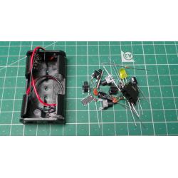
Parts list:
R1, R2 - 10K
C1 - 10u
C2, C3 - 30p
C4 - 100n
PR1 - 1K
Y1 - 12MHz
U1 - STC11FC2
S1, S2 - microswitch
LS1 - piezo
Q1 - 8550
DS1 - display
J1 - terminal block
socket DIL20 1 pc
circuit board
Reviews
No customer reviews for the moment.
30 other products in the same category:
-
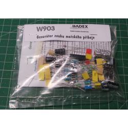
Sea and...
6,48€
-
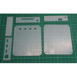
Acrylic...
7,31€
-
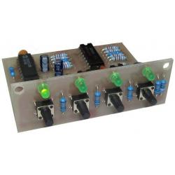
4 Input...
8,85€
-
Stereo...
11,06€
-
Reversing...
4,43€
-
Triac...
1,35€
-
16 sounds...
3,48€
-
18W Mono...
2,71€
-
Metal...
2,77€
-
Stereo 6J1...
17,37€
-
Acrylic...
4,50€
-
Hourglass...
3,08€
-
Magic eye...
16,34€
-
Wireless...
3,87€
-
Preamplifie...
3,87€
-
Pocket AM /...
8,30€
-
Sound...
2,13€
-
Strobe, 12V...
5,45€
-
GPRS...
5,52€
-
Function...
2,85€
-
Tilt /...
3,08€
-
FM receiver...
4,66€
-
Variable...
8,30€
-
Stereo...
5,85€
-
LED Fidget...
8,53€
-

Bubble...
11,77€
-
Power...
5,69€
-
Running...
1,43€
-
5 Band...
8,53€
-
Reflective...
4,66€
